Updated 11/16/2013
Our summer 2013 project is an antenna test range behind the barn. Top is 35 feet above ground to simulate the typical emergency fixed base or field day deployment. The first project is testing various feed points and various balun's to create the ideal Off Center Fed ( Windom ) Dipole. To see what I build for my base antenna setup follow this link to my Windom Fan Dipole on my Shack Page.
All tests below were made with the Windom (OCF) designed for a feed point of 37.8% from one end. Actual lengths of wire were 123' 9" total. Short end 46' 10". Long end 76' 11". Wire was 14 gage stranded PVC covered. There was no attempt made to balance the lengths to achieve a dip closer to the center of the 80 Meter band as I wanted a constant wire standard between each type of balun.
I have test results for feed points of 20% and 32% from one end per information from various manufacturers and experimenters. A lot of clams for these non standard feed points include better multi band operation. I could not duplicate any of these claims and found the standard 37.8% feed point produced the most constant results using various balun's. I realize 35' is a little low for an 80 Meter dipole however, these tests were to find the ideal antenna for field deployment and 35' is a good average height for what you can find in the field to hang an antenna on or the push up fiberglass poles I use. ( Naturally there are other views on this feed point issue. See http://hamwaves.com/cl-ocfd/en/index.html I just could not duplicate their measurements.)
Just for fun I ran tests at 20' elevation. Not much changes. A little different feed point |Z| and a slight change in the resonant point. What's really interesting is wen you move from my high desert, very dry, decomposed granite ground, to a city parking lot the frequency of the resonant dip changes considerably. You really need an analyzer of some type to fine tune your antenna lengths for different physical locations. Also see Yes or No Torroids?
Communications Trailer OCF (New 11/5/13)
Amidon Core Guanella 4 to 1 balun
Putty Knife wireman Core 4 to 1 voltage balun
Palomar Core 4 to 1 voltage balun
Metal vs. fiberglass masts.
Mast Effect
My Base Station OCF Fan Dipole
QST Article on OCF Antennas (pdf
Article in IEEE Antennas and Propagation Magazine · February
2015
Near Vertical Incidence Skywave
Propagation: Elevation Angles and
Optimum Antenna Height for Horizontal
Dipole Antennas
Also, see our How Antennas Work Reference
Page
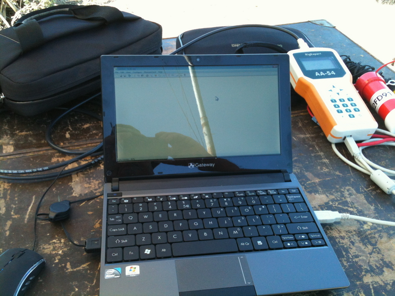
Here is our test table with the RigExpert AA-54 analyzer connected to a Notebook running Windows 7
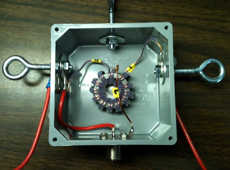
Typical balun. This is a 4 to 1 with 12 turns of #16 Teflon covered magnet wire on a Palomar F140-6 core. The ideal, according to what you read on the Internet, is 14 turns but I ran out of room. Housed in a weatherproof electrical box from Lowes.
This is my Guanella balun built from the Amidon FT-240K core. Wound
per instructions in their Transmission Line Transformers Handbook page 31.
Amidon sells a kit
with the core, wire, Teflon, and book.
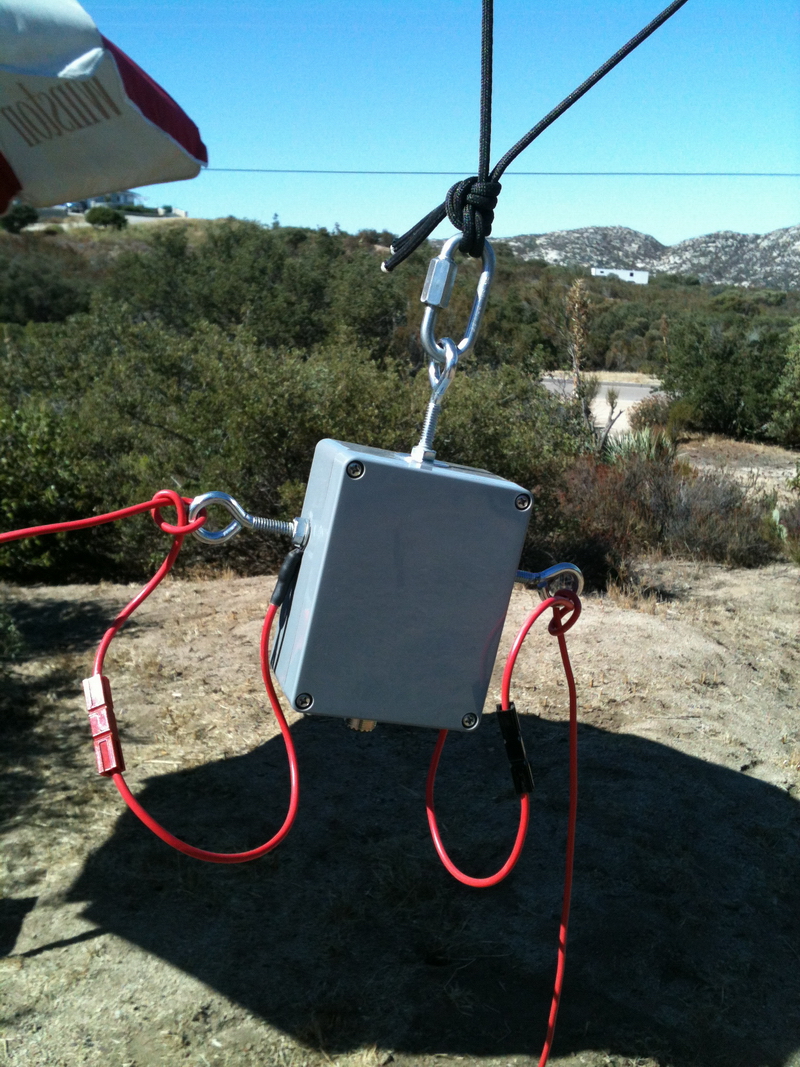
I am using power poles so I can change out balun's easily. Don't recommend them for your permanent antenna setup.
The idea behind the "Carolina" Windom (OCF) Dipole is using the vertical portion of the feed line from the 4/1 balun to the ground as a common mode radiator. To do this you need to put a common mode current choke on the coax feed line to keep the common mode currents out of your shack. The common way to accomplish this is with clamp on torroids at the bottom of your support mast or X number of feet from the balun. Google the subject and you will see lots of different "expert" opinions. Further, you will see a lot of information from manufacturers who say their 4/1 balun's do not need a common mode choke as they do it in the balun. ( Then that would be a regular not a Carolina Windom.)
My experience with these antennas is there are different results, VSWR, points of resonance, with and without the torroids. I always use and test with clamp on torroids. To see what I mean below is a chart from the "Putty Knife" 4/1 I use in my portable antennas. ( Click on the graph for a larger version.)
The dark graph is with 7ea clamp on torroids. The coax is run twice
through the torroids to increase their impedance.
As you can see there is quite a change in the points of resonance with and without them.